The OSI Model
From geeksforgeeks
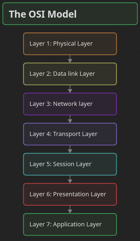
The OSI Model is a conceptual framework created by the International Organization for Standardization (ISO) to describe how data is transmitted across a network using a structured seven-layer architecture.
- Divides network communication into seven functional layers.
- Assigns specific responsibilities to each layer.
- Promotes compatibility between different networking systems.
- Simplifies network design, implementation, and troubleshooting.
An easy way to remember the layers is to recite the following Mnemonic:
- Please Do Not Throw Sausage Pizza Away
See below:
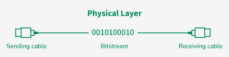
Layer 1: Physical Layer
This is the lowest layer of the OSI reference model and responsible for the actual physical connection between the devices.
- Physical Layer is responsible for transmitting individual bits from one node to the next.
- When receiving data, this layer will get the signal received and convert it into 0s and 1s and send them to the Data Link layer.
- Common physical layer devices are Hub, Repeater, Modem, and Cables.
Functions
- Bit Synchronization: This layer provides the synchronization of the bits by providing a clock and that clock controls both sender and receiver, thus providing synchronization at the bit level.
- Bit Rate Control: This layer defines the transmission rate i.e. the number of bits sent per second.
- Physical Topologies: Specifies how the different, devices/nodes are arranged in a network i.e. bus topology, star topology, or mesh topology.
- Transmission Mode: Defines how data flows between the two connected devices and the various transmission modes possible are Simplex, half-duplex and full duplex.
Layer 2: Data Link Layer (DLL)
The data link layer is responsible for the node-to-node delivery of the message and make sure data transfer is error-free from one node to another, over the physical layer.
- When a packet arrives in a network, it is the responsibility of the DLL to transmit it to the host using its MAC address.
- Packet in the DLL is referred to as Frame and Switches and Bridges are common DLL devices.
- The packet received from the Network layer is further divided into frames depending on the frame size of the NIC (Network Interface Card).
- DLL also encapsulates Sender and Receiver’s MAC address in the header.
Sublayers of Data Link Layer
- Logical Link Control (LLC): Manages communication between upper layers and performs error and flow control.
- Media Access Control (MAC): Controls how devices gain access to the transmission medium and use MAC addressing.
Functions
- Framing: Framing is a function of the Data Link Layer that divides data into frames by adding start and end bits so the receiver can identify each unit of data.
- Physical Addressing: After creating frames, the Data Link Layer adds MAC addresses of the sender and receiver in the header to ensure correct delivery.
- Error Control: The Data Link Layer detects and retransmits damaged or lost frames to ensure reliable communication.
- Flow Control: Flow control manages the data transmission rate so the sender does not overwhelm the receiver.
- Access Control: The MAC sublayer decides which device can transmit data when multiple devices share the same communication channel.
Layer 3: Network Layer
The Network Layer works for the transmission of data from one host to the other located in different networks and also takes care of packet routing.
- The sender and receiver's IP address are placed in the header by the network layer.
- Segment in the Network layer are referred to as Packets****.****
- Network layer is implemented by networking devices such as routers and switches.
Functions
- Routing: The network layer protocols determine which route is suitable from source to destination.
- Logical Addressing: The Network Layer assigns unique IP addresses to sender and receiver so devices can be identified across different networks.
Layer 4: Transport Layer
This layer is responsible for end-to-end delivery of the message and Transport Layer provides services to the application layer and takes services from the network layer.
- The data in the transport layer is referred to as Segments and it is responsible for successful data transmission.
- Protocols used in Transport Layer are TCP, UDP NetBIOS, PPTP.
- It adds source and destination port number in its header and forwards the segmented data to the Network Layer.
- Example: When a web application requests a web server, it typically uses port number 80, because this is the default port assigned to web applications.
Functions
- Segmentation and Reassembly: The Transport Layer divides the message into smaller segments and reassembles them at the destination.
- Service Point Addressing: The Transport Layer uses port numbers to ensure the message is delivered to the correct process on the destination device.
Services
- Connection-Oriented Service: Establishes a connection before data transfer and ensures reliable delivery with error checking and acknowledgments.
- Connectionless Service: Sends data without establishing a connection, providing faster but less reliable communication
Layer 5: Session Layer
Session Layer is responsible for the establishment of connections, management of connections, terminations of sessions between two devices and provides authentication and security.
Functions
- Session Establishment, Maintenance, and Termination: The layer allows the two processes to establish, use, and terminate a connection.
- Synchronization: This layer allows a process to add checkpoints that are considered synchronization points in the data.
- These synchronization points help to identify the error so that the data is re-synchronized properly
- Dialog Controller: The session layer allows two systems to start communication with each other in half-duplex or full duplex.
Example
Let us consider a scenario where a user wants to send a message through some Messenger application running in their browser. The “Messenger” here acts as the application layer which provides the user with an interface to create the data. This message or so-called Data is compressed, optionally encrypted (if the data is sensitive), and converted into bits (0’s and 1’s) so that it can be transmitted.
Layer 6: Presentation Layer
The Presentation Layer is also called the Translation layer and data from the application layer is extracted here and manipulated as per the required format to transmit over the network.
- Protocols used in the Presentation Layer are TLS/SSL (Transport Layer Security / Secure Sockets Layer).
- JPEG, MPEG, GIF, are standards or formats used for encoding data, which is part of the presentation layer’s role.
Functions
- Encryption/ Decryption: Data encryption translates the data into another form or code. The encrypted data is known as the ciphertext, and the decrypted data is known as plain text.
- A key value is used for encrypting as well as decrypting data.
- Compression: Reduces the number of bits that need to be transmitted on the network.
Layer 7: Application Layer
At the very top of the OSI Reference Model stack of layers, we find the Application Layer which is implemented by the network applications. These applications produce the data to be transferred over the network.
- This layer also serves as a window for the application services to access the network and for displaying information.
- Protocols used in the Application layer are SMTP, FTP, DNS, etc.
Functions
- Network Virtual Terminal (NVT): It allows a user to log on to a remote host.
- File Transfer Access and Management (FTAM): This application allows a user to access, retrieve and manage or control files from a remote computer. .
- Directory Services: This application provides distributed database sources and access for global information about various objects and services.
Data Flows in the OSI Model
When we transfer information from one device to another, it travels through 7 layers of OSI model. First data travels down through 7 layers from the sender's end and then climbs back 7 layers on the receiver's end. Data flows through the OSI model in a step-by-step process:
- Application Layer: Applications create the data.
- Presentation Layer: Data is formatted and encrypted.
- Session Layer: Connections are established and managed.
- Transport Layer: Data is broken into segments for reliable delivery.
- Network Layer: Segments are packaged into packets and routed.
- Data Link Layer: Packets are framed and sent to the next device.
- Physical Layer: Frames are converted into bits and transmitted physically.
Each layer adds specific information to ensure the data reaches its destination correctly, and these steps are reversed upon arrival.
Example
We can understand how data flows through OSI Model with the help of an example mentioned below. Let us suppose, Person A sends an e-mail to his friend Person B.
- Step 1: Person A interacts with e-mail application like Gmail, outlook, etc. Writes his email to send. (This happens at Application Layer).
- Step 2: At Presentation Layer, Mail application prepares for data transmission like encrypting data and formatting it for transmission.
- Step 3: At Session Layer, there is a connection established between the sender and receiver on the internet.
- Step 4: At Transport Layer, Email data is broken into smaller segments. It adds sequence number and error-checking information to maintain the reliability of the information.
- Step 5: At Network Layer, addressing of packets is done in order to find the best route for transfer.
- Step 6: At Data Link Layer, data packets are encapsulated into frames, then MAC address is added for local devices and then it checks for error using error detection.
- Step 7: At Physical Layer, Frames are transmitted in the form of electrical/ optical signals over a physical network medium like ethernet cable or WiFi.
After the email reaches the receiver i.e. Person B, the process will reverse and decrypt the e-mail content. At last, the email will be shown on Person B email client.
Electric Meatball's Digital Garden Home
Terminology📖
The TCP IP Model